The purpose of control systems is to limit the torque and the power experienced by the drive train in order to increase lifetime. The drive trains suffers from fatigue due to aerodynamic and structural loads. The structural strength of the wind turbine can be maintained up to a certain wind speed. Once this so-called cut-off wind speed is reached, rotation needs to be constrained.

Generator Basics
Wind turbines have been assisting mankind to convert the energy contained in wind into electricity for the last 50 years. This has been possible due to blades using state-of-the-art aerodynamic analysis and generators. The job of the generator is to convert the mechanical energy from the turning blades into electrical power for use in domestic power or to charge batteries.
How does moving air generate electric energy?
One of the most basic principles in physics is that energy can be neither produced nor destroyed. Instead, it can only be converted from one energy form into another. Applying this to wind turbines, we see that they do not in fact generate energy. To understand what they do exactly, it is important to know what different kinds of energy are involved in the process.
First, there is translatory kinetic energy. This form of energy is contained in any object or fluid that moves from one place to another. In our case, the translatory kinetic energy is contained in moving air, more precisely in wind. By clever design, we can build a machine that converts this translatory motion into a rotatory one. Doing this, we also transform the translatory kinetic energy into rotatory kinetic energy. An easy way to understand rotatory energy is imagining to hold a pencil in your hand and twisting it. By doing this, the pencil does not chance its place but rotates around an axis. In a wind turbine, the equivalent of the pencil is a shaft. The machine converting the translatory into rotatory motion is of course made up of the wind turbine rotor blades.
The second step is converting this rotatory kinetic energy into electric energy. In a nutshell, electric energy consists of moving electrons. This means that now, we need to build a machine that will take a rotating shaft and use it to produce a motion of electrons that will become an electric current. This machine is called a generator.
So in a nutshell, a wind turbine contains two energy transformation processes: One takes place in the blades and the other in the generator, both of them being essential parts of the system.
Electricity is produced by electromagnetic Induction
The physical phenomenon that allows for an electric current to by generated by some kind of motion is called electromagnetic induction. In our everyday lives, we know induction applications in the context of induction cooking appliances. The concept behind these two pieces of technology is essentially the same.
Essentially, if you take a wire and move it within a magnetic field, it induces a current. The other way round, if you run an electric current through a wire, it will also create a magnetic field. This was discovered by Michael Faraday in 1831. So how exactly does this work inside a generator?
Using Faraday’s Law
The first law of physics that will help to understand the process is the law of the Lorentz Force, also known as the Right Hand Rule. If you have a look at your right hand and stretch out your thumb, index finger and middle finger so that they are perpendicular to each other, imagine that the thumb represents the direction of the motion of an electric load carrier, such as an electron and the index finger represents the direction of a magnetic field. The Lorentz Force Law now says that there will be a force induced by the motion of the electron and that this force will point in the direction of your middle finger.
Moving a wire in the exact same way just means moving not a single electron, but many of them. Because of the Lorentz Force, they will all get pushed in the same direction. Consequently, they will move through the wire. Now, this is already electricity, since an electric current is essentially just electrons that are moving.
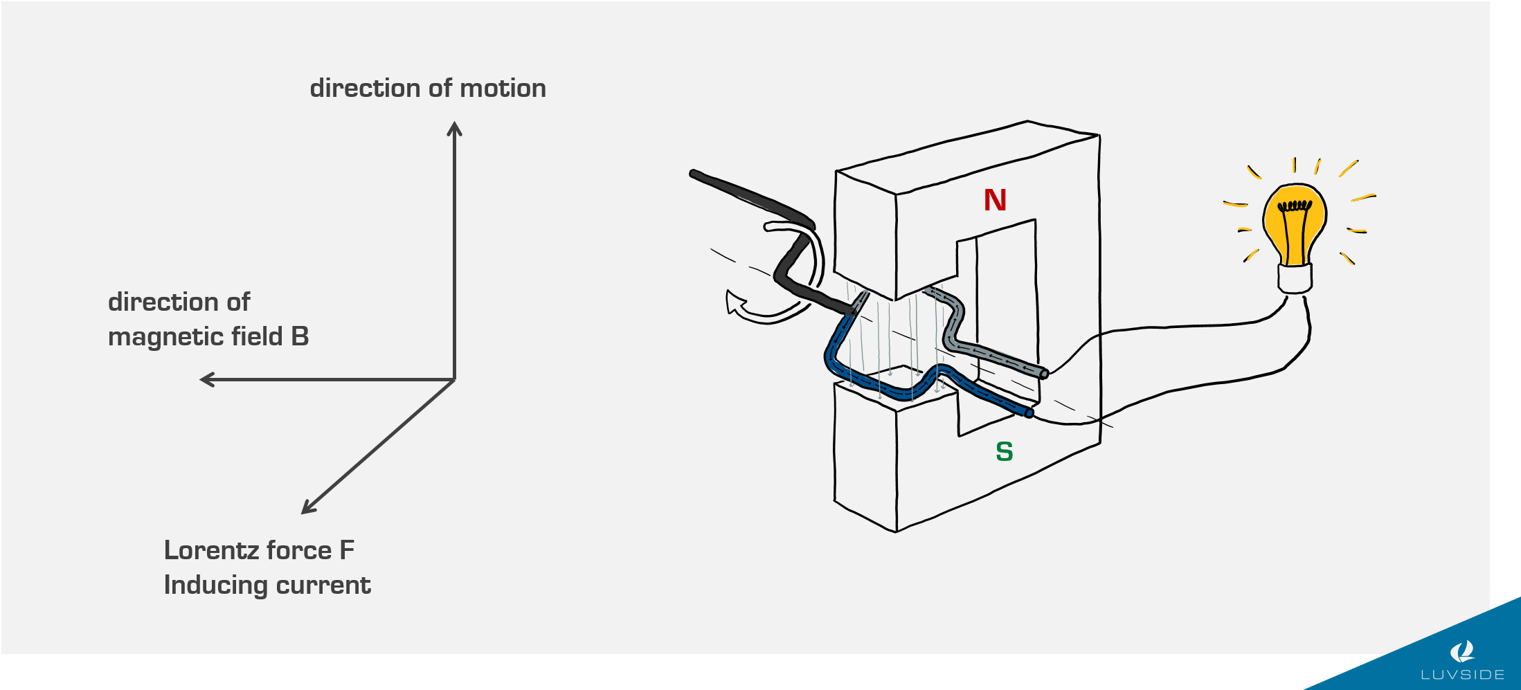
Generators make use of this observation. The first step to build a generator is not to use a straight wire, but to bend it so that it forms a loop. This looped wire is called a coil. To make the electricity produced visible, we add a light bulb to the coil. Next, we attach a handle (or a wind turbine) to the coil so that we can make it rotate. The last part that is needed is a magnetic field that we create by placing a (horseshoe) magnet around the coil. Note: the direction of a magnetic field always points from the northern to the southern pole. In the case of the image below, this means that the magnetic field points downwards.
So let’s say that the coil rotates clockwise. For light grey part in the image, this means that it is moving to the right, while the blue part is moving to the left. Applying the Right Hand Rule, we can figure out that in the grey part of the wire, the current will flow ‘backwards’, while in the blue part, it points ‘to the front’.

Alternating Current is the simplest to generate
The direction of the current flow is key to understanding why the simple generator setup presented above produces not direct current (DC) but alternating current (AC). As you may know, DC is characterised by a unidirectional flow of electric charge. This is what happens when the electrons in a conductor all move in the same direction and most importantly will not change this direction over time. If they do in fact change their direction and oscillate back and forth, we are looking at an AC current. So why is the latter produced here?
When the coil rotates, the grey part will at some time reach a point that is the furthest right it can get. After this point, it will start moving left. But if the wire moves to the left, the Right Hand Rule tells us that the current flow needs to be in the ‘backwards’ direction. That is what we observed in the blue wire before. Similarly, the blue wire will start moving to the right and the current flow in that part will also change. So we see that every half turn, the direction of the current reverses. This the exact observation typical of an AC current.
Of course, it is also possible to generate DC power. In fact, it is not even that much more complicated if you use a few simple technological tricks. To read more about those, have a look at the second part of this article here.
Stator and Rotor
In the context of wind turbines, you will oftentimes hear the terms ‘stator’ and ‘rotor’. These are not exactly generator components but a unit of several components each.
Stator
The term ‘stator’ is derived from the word ‘stationary’. It describes all the generator parts that will not move even when the generator produces energy. In the very basic setup that was described above, the stator would be the horseshoe magnet that was placed outside of the coil. In most modern generators though, the stator consists of the coils. Essentially, the basic setup is flipped around.
Rotor
The rotor of a generator is the part of it that moves. Typically, the stator is placed outside, and the rotor moves inside of it. As discussed before, the stator will usually hold the coils. Vice versa, this means that the rotor contains the magnets and creates the magnetic field. The magnets can either be mounted on the rotor’s surface, embedded into the surface od installed inside the rotor.
Consequently, the magnetic field cuts across the conductors, generating an induced current, as the mechanical input causes the rotor to turn. So what is said mechanical input? Simply put, it is our wind turbine shaft. An important point to note though, is that the shaft rotation created by the turbine blades cannot be directly coupled to a generator. This is because the blades usually turn at a very low rate. This slow speed rotation is not sufficient to produce any meaningful electricity. Therefore, before connecting to the generator, the speed is increased in a gearbox, which usually uses a planetary gear set arrangement to achieve the high-speed ratio (e.g. 1:20 for small VAWTs). When picking a generator to work with a wind turbine, this generator-shaft interface is a crucial point to consider.
Another detail to note: The distance between the rotor and the stator should preferably be small. There are two reasons for this:
To maximise the generator’s efficiency, since larger distances would produce unwanted eddy currents.
- To minimise the amount of rare earth materials needed in the magnets.
Generator Components
As seen before, the simplest generator is a two-pole (one north and one south pole) rotor with the stator connected to the grid. The number of phases and frequency of the AC current are usually fixed because they need to be adapted to the grid. In the case of the European grid, the parameters that need to be met are single phase and a frequency od 50 Hz. What exactly does this mean and how does it relate to the structure of a generator?
Poles
As discussed above, the simplest generator that can be built will produce an AC current. While in theory, this kind of current can take on a variety of different forms, it can commonly look like a simple sine curve. In order to put its shape in concrete terms, we can use two different characteristics of it: amplitude and frequency.
Essentially, the amplitude determines how high the curve’s ‘mountains’ and how low its ‘valleys’ are. These values correspond to the voltage output. The frequency is even more important. It signifies how many highs and lows the runs through in a specific amount of time. As mentioned above, it is crucial to control the frequency of the generator’s power output precisely because otherwise, it is not allowed to be connected to the grid. The fact that puts this to a challenge is that generally speaking, the frequency is directly interconnected to the turning speed of the rotor shaft inside the generator. Especially in wind turbine applications, this is again interconnected to the turning speed of the rotor blades. Considering that most turbines will face a variety of different wind conditions over their lifetime, including both lull and storms, it is clear that we need to be able to control how much of the rotational speed is transmitted from the turbine to the generator.
Moreover, this is not the only challenge concerning the frequency. Even after the first problem is dealt with and the rotor turns at a constant speed, the resulting frequency is usually much lower than 50 Hz. In theory, it might be possible to use another gearbox to deal with this. Much simpler though is the following: instead of just two poles, we use a higher number like six. What will happen is that the coils experience a correspondingly higher number of magnetic field run-throughs, although the turning speed has not in fact changed.
Coils
Generally speaking, there is one more characteristic that distinguishes different kinds of AC electricity: it is the number of its phases. Like we already saw, AC can consist of a sine curve. While this is true, it does not in fact have to be exactly one sine curve. A common type of current is one that contains three different sine curves that have a small temporal offset. So if at some moment in time, one sine curve reaches its peak height, it will take the second curve a small amount of time to reach the same height and the third curve even more.
The technical implementation to create this type of current is actually quite simple: we simply do not use just one coil in the generator, but as many as the number of phases that we need. The coils are placed with an angular offset to each other, so that the magnetic fields run through them one after the other.
Die technische Umsetzung, um diese Art von Strom zu erzeugen, ist eigentlich ganz einfach: Im Generator verwendet man nun nicht mehr nur eine Soule, sondern so viele wie die Anzahl an Phasen, die man erzeugen möchte. Die Spulen ordnet man winkelversetzt zueinander an, sodass das Magnetfeld sie nacheinander durchläuft.
Slip Rings
The need for the use of slip rings might not seem obvious at first but becomes clear when you consider that a generator combines both rotating and static components and that it needs to provide closed electric circuits. If you just took some cables to connect the rotating part of a circuit to the static one, it is not difficult to imagine they will end up extremely tangled and break. This problem is solved by using slip rings.
In a nutshell, slip sings are cylindric rings that are attached to rotating cables so that they rotate along with them. The rings’ rotation is, however, much easier to handle. Using very simple, static counter pieces that are placed at the perimeter of the cylindric rings, the circuits can be closed.
Brake
The generator brake is used to protect the machine against overload damage. Typical brakes used are called power-off brakes. They consist of electromechanical discs that can only be released through the supply of a specific voltage. In case of interruption of the power or voltage supply, the brake closes automatically. This means that when the rotor blades are not turning and generating energy, for example during assembly, transport and maintenance, the shaft is in fact fixed. It is therefore a safety mechanism.
In addition, there are internal control electronics that actuate the brake automatically if a risk of overload is detected. Those can be in regard to permissible temperature, voltage or rotational speeds. In case of excessively windy conditions, the brake is usually also activated to arrest the blade rotation.
Power electronics
Most generators have built-in sensors that monitor the heat development (temperature), current and voltage as well as the turning speed of the machine. When the limit values are reached, the torque is automatically adjusted to zero and the brake is activated. The reactivation of the brake can be executed either via restart or via a communication point.
Control Systems
Related Content
Since centuries ago, humans have learned to utilize wind power for activities ranging from everyday tasks like grinding grains to long-distance traveling such as sailing....
Horizontal axis wind turbines are what most people picture when talking about wind turbines— the gigantic, white fans standing along the coastlines or across vast...

